Project 2019_A - design, preparation and print
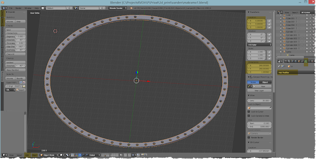
Let's start with a solid ring creation and let's call it part X. The ring is surrounded by 66 holes . The holes are in the same distance to each other. So it is even better to include the holes in the print job as drilling them manually afterwards. The ring is designed using BLENDER and its inner diameter is 251 mm and the outer 266 mm. This dimension plus a buffer for the - so called - "brim" around the circle will nearly fill out the maximum print capabilites of the 3D print bed. The print bed - the plateau to print on - has a dimension of 300 mm x 300 mm.
Steps to perform - written down one time in detail
1a) the solid ring
1b) the holes in the solid ring
1c) get rid of the cylinders - they should leave holes.
1d) export the ring as a STL file for the print preparation

1e) prepare the print - create GCODE print instructions

even more parts...
2) Pistons


 3) con-rods
 4) surface / ground plateau
 5) rotor (vertical mirrored)
 Some small parts aren't listed.
This has been done in the first month and in the winter time of 2019.
It was making fun to work with Blender, Cura and to print and prepare the parts of the model.
Finally all parts were assembled to build a bigger model. Some bearings were plugged in and a few small aluminium rods sticked into the holes to join the moving parts.
Steps to perform - written down one time in detail
1a) the solid ring
- open blender, remove default circle by pressing x
- press shift+c and center the cursor to 0,0,0 by selecting 'cursor to center'
- press num block 7 to view from top on the surface
- click add -> mesh -> circle
- add a ring - on the left panel choose 96 vertices, radius 133 (mm)
- press num block comma to center the current object and see the full dimension
- click add -> mesh -> circle
- add a ring - on the left panel choose 96 vertices, radius 125.5 (mm)
- hold shift and click with the right mouse button on the other ring (both are marked now)
- join both rings together to one object by pressing CTRL+j (now are both in the same orange color)
- press tab and switch to edit mode (all vertices should be highlighted, press 'a' if not)
- press 'w' and select 'bridge edge loops' to fill the inner area between both circles.
- press tab to leave edit mode and swap to object mode
- press num block '1' to change the perspective to the front view
- press 'n' to see the location and transform values of the object (our flat filled ring so far)
- press shift+d to duplicate the ring
- set the location of the new rint to 0,0,2 (x,y,z). Hence levitates the new ring 2 mm above the first one which is still on position 0,0,0.
- hold the left mousebutton and change the perspective in order to see the silhouette of both rings.
- move the mouse to the not selected ring, hold shift and press the right mouse button to select this object as well.
- now join both rings together by pressing CRTL+j
- press num block '7' to look like a bird from above on the flat lying rings again.
- press tab for the edit mode
- press 'a' to deselect all vertices (the vertices are black now instead orange)
- click on the center of the axis
- press 'c' to act with the mouse pointer as a circular selecting cursor.
- roll the mouse wheel down to you in order to increase the diameter of the selecting round cursor.
- roll on till the cursor is bright enough to overlay only the inner diameter of our joined ring object.
- press the left mouse button to select all inner vertices then.
- press 'w' and choose 'bridge edge loops' and connect the lower ring with the upper ring on the inner side. Now remains the ring only open on the outer side. We will close it, too.
- press num block '7' if needed to look from top again
- press tab to leave edit mode for a moment
- press 'z' to swap from wireframe object view to solid object view.
- hold the left mouse button and play with your viewpoint and rotate the object.
- after playing press num block '7' one more time.
- enter edit mode by pressing tab
- press 'a' and deselect all vertices (black on grey)
- press 'c' or 'b' to choose the selecting cursor of your choice and select only the outer vertices. By pressing 'b' for a blockwise selection (instead c like circular) hold the left mouse button and move the mouse pointer for the selection.
- when all vertices of the outer diameter are marked again, press 'w' and execute 'bridge edge loops' and close the vertices/combine them. Now is the ring solid. All edges are closed.
- ensure to be in edit mode (the tab key)
- select all vertices (press 'a' if needed)
- press CTRL+t to triangulate the object. Each quader face will be intersected to triangle faces.
- press CTRL+f and try to fill it on top.
1b) the holes in the solid ring
- press shift+c and center the cursor to 0,0,0
- no edit mode (tab), ensure object mode
- add -> mesh -> cylinder (64 vertices, radius 2.5, Depth 20 ; see the options on the left panel)
- The dimension of the cylinder is now 5,5,20 (press 'n' and look under Dimensions)
- The the location of the cylinder to 0, 129.5, 0. Now is the cylinder in the middle of solid ring surface. Because the cylinder is very tall (20 mm Depth) it is like a needle in the solid ring.
- The solid ring should be surrounded by 66 of those cylinders.
- To do so it is required to move the origin of the cylinder to the middle position of the solid ring which is 0,0,0. Then it is possible to spin the cylinder 66 time around the origin.
- center the pointer by pressing shift+c to 0,0,0 (the cylinder object is still marked - right mouse btn click)
- click 'Object' (left bottom area) -> 'Transform' -> 'Origin to 3d cursor'
- goto edit mode by pressing tab
- click on 'Tools' (left top area - vertical tab called 'Tools')
- choose 'Spin' and look more down to the spin detail panel.
- Over there set Steps to 66 and angle to 360
- press tab to leave the edit mode- you will see 66 orange circles on the solid ring silhouette
1c) get rid of the cylinders - they should leave holes.
- This is done by applying a Boolean difference modifier.
- Select the solid ring by marking it with a right mouse button click.
- on the right side panel click on the small tool buttons of modifiers (a bit hidden if you apply the first time).
- click 'add modifier'
- choose boolean modifier
- select operation difference
- select object by using the pin feature. Click on the small symbol and then select the cylinder object via a left mouse btn click.
- then click 'Apply'
- press 'z' and change to solid object view.
- left mouse button click to select the cylinder
- press 'g' and move the cylinders object to anywhere outside of the ring. press left mouse btn again.
- press 'x' to remove the cylinders object.
- it is done - the inner solid ring is surrounded by 66 with a certain distance.

1d) export the ring as a STL file for the print preparation
- enable the '3D printing' feature in the preferences of blender if not done. (pull down menu, user preferences, add ons)
- when the ring is selected (right mouse btn), open the vertical tab on the left '3D printing'
- click on 'Make manifold'
- click on 'Export' to create the proper STL file.

1e) prepare the print - create GCODE print instructions
- open CURA (Version 3.6.0 used here)
- open the exported STL file using the pull down menu in the left top corner
- you will see the object lying on the virtual print surface of CURA.
- click on 'prepare' btn in the right bottom corner
- in the top change the view to layer viewer - use the list button
- now slice through the printing process by selecting layer by layer using the slicing selector.
- Modify the CURA setting to perform a suitable printjob.

2) Pistons


This has been done in the first month and in the winter time of 2019.
It was making fun to work with Blender, Cura and to print and prepare the parts of the model.
Finally all parts were assembled to build a bigger model. Some bearings were plugged in and a few small aluminium rods sticked into the holes to join the moving parts.

Kommentare
Kommentar veröffentlichen